A New Bridge for South AfricaItalian know how and technology for a south-african main work: the Cornubia boulevard overpass
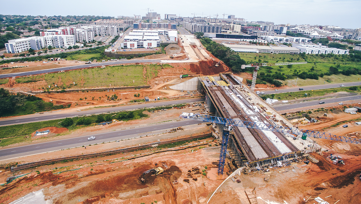
The South African branch of the Italian construction company CMC di Ravenna has chosen Pilosio's solutions for the construction of a new bridge in Durban, project name N2/ Cornubia Interchange. This overpass will serve to streamline traffic by linking the Umhlanga industrial zone with the Cornubia new development area (Tongat). Recently, the two companies have already been working with mutual satisfaction in the construction of the major Mount Edgecombe Interchange motorway junction, which included two of the longest viaducts in the country.
Technical Partnership
Thanks to technical skills acquired over the years in the infrastructures sector, Pilosio was again chosen as a partner for the type of solutions proposed, the quality of the products, not to mention the support and assistance offered during design and during all the delicate stages on site. Considering that Pilosio studied and provided to CMC a custom made system for another bridge, Pilosio engineers collaborated with CMC ones to reuse the same system. The idea was to use a tried and tested system and exploit their assets. Moreover, competitors offered other solutions, meaning non-reusable wooden ribs. The Cornubia Boulevard Overpass is a three-box, cast-in-situ concrete deck of 127,0m length, divided into three spans.
Photo Gallery: from design to construction

Complexities
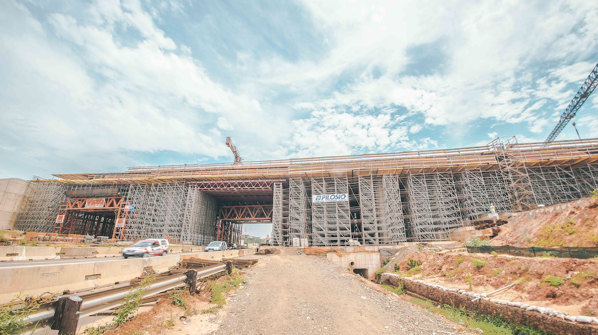
One of the complexity of the project lies on the fact that the construction of the bridge have to take place without interrupting the normal traffic flow of the highway. This led to the construction of large portholes above the highway to allow for the preassembling of formworks panels, installing of the rebars and deck casting operations in a complete safety process. Another main complexity for the construction lies on the fact that the viaduct has a longitudinal slope of 2.4°, a transversal slope of the cross section plus a pre-camber casting deck.
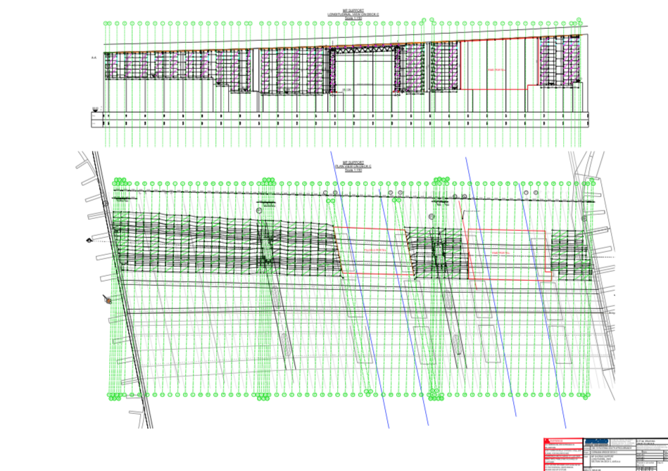
Porthole Support
MP Heavy-duty support system was provided for portholes support in order to overpass the highway: HD Walls of 19.20m long and 12.27m high spanning a clearance of 16.0m and with a total load capacity of 1,451kN. The deck and the wings of the bridge were poured on plywood surface installed on a grid of secondary timber beams and main steel walings (double UPN100 profiles) formwork. (In case of structures that has to over pass the roads). In this case, the deck of the bridge was installed over supporting truss beams 150cm high, made of HE340A and double L-shaped beams, coupled by vertical braces.
Adjustable foot plates, placed between the steel walings of the bridge deck and the trusses, allowed to give pre-camber to the casting. The steel trusses were supported by steel beams placed over MP Heavy Duty towers. In the horizontal plane, the trusses were stiffened by means of tube and fittings, both on the upper and on the lower cords of the trusses. The stresses in the steel elements of main beams and the nodal reactions were obtained from 3D FEM dedicated model of the structure, carried out with SAP2000 software. All the static checks were carried out by Pilosio engineers according to EN 1993 Standard.
Adjustable Foot Plates
The foot plate extraction had to guarantee the transversal sloping of the cross section plus the pre-camber that allows the casting to have horizontal bottom deck after falsework dismantling. The pre-camber was obtained from 3D FEM model of the supporting structure.
Viaduct Sloping
The gross longitudinal sloping of the bridge of 2.4° was obtained with the inclination of the main trusses. The steel trusses were fixed on the left support of the portal (bolt connection) and free to move horizontally on the right support. Thus, the horizontal action due to sloping were all applied on the left support (MP Heavy Duty support tower). The MP Heavy Duty tower base jacks were fixed to the ground and braced to the lateral MP standard platform in order to avoid any tipping risk. As an alternative, cables or ballast could be placed.
Lateral Support Platforms
As temporary support platform, MP Pilosio multidirectional shoring system fitted perfectly with all the site requirements. The support platforms was obtained by connecting square or rectangular modules together. Height varies from 6,5m to 12,7m was easily covered thanks to the flexibility of the MP system. Different capacities were reached with various configurations of braces and ledgers.
Deck
Two casting phases were performed: the first phase is the pouring of the bottom deck and the second phase is the pour of the lateral vertical walls and upper slab with lateral wings. For the deck casting, the builder chosen Maximix, a formwork system made of wooden beams, steel beams and plywood panels that allows to cover large surfaces to be run in site and complex shapes with high capacity and limited weight. The capacity can be adapted to the requirements of the project by varying the distance of the beams. Pilosio engineers made the design of the wooden deck.
On Site Assistance
Pilosio gave on site assistance with training for assembling Maximix panels, providing dedicated shop drawings for each single module (often typical designs require an interpretation of the workers on site) and day by day assistance for the various problems during the assembly and installation of the MP towers to remedy any discrepancies detected on site with respect to the measurements made previously.
Featured articles


Partner